One shot field balancing on 41 MW steam turbine with pipe strain problem
- NK

- Jun 8, 2023
- 4 min read
Updated: Jun 9, 2023
We were engaged to perform vibration measurement and analysis of a 41 MW steam turbine and generator as the excessive vibration amplitude was measured at Bearing 2 during the load variation test. Details vibration data analysis suggested that the main root cause is due to high-pressure (HP) steam inlet pipe strain resulting in turbine casing distortion, hence, altering rotor-bearing dynamic stiffness at different load conditions. However, there was no time slot for maintenance and correction activity due to plant operation constraints. A compromise field balancing was proposed to the customer. The optimal field balancing weight was calculated and it was able to reduce the vibration amplitudes down below the setpoint within one shot.
The unit received an outage between September to October 2022. The entire reduction gear was replaced by the refurbished unit. The LP rotor was removed for inspection, and axial distortions were found on stage 4 blade shrouds of the LP rotor and were kept as they were. The LP rotor was low-speed shop balanced at the last stage blade balancing plane. All turbines and generator bearings were replaced with the original ones and all couplings were aligned. It was found during the outage that the HP exhaust pipe’s flange was offset to the left of the turbine’s flange, looking from the turbine to the generator. The pipe was forced to make both flanges aligned. The unit was startup on 13 October 2022 but tripped on the day after from a high vibration at 35 MW due to rubbing induced rotor bow at Bearing 1 (HP inlet). A field balancing was done by placing the weights at the HP rotor coupling and the LP rotor coupling and the unit was uneventfully continuing the operation afterward. However, the unit encountered a trip from shaft vibration at Bearing 2 (HP exhaust), and the loss of Bearing 1YD vibration signal in February 2023 due to a faulty sensor system. The trip setpoint of Bearing 2 was raised temporarily to allow the operation. During our on-site vibration measurement on 18 April 2023, it was observed that the temperature in the vicinity of the HP turbine exhaust bearing was excessive and the gland steam and vacuum issues were revealed by the plant’s maintenance personnel.
Machine description
The machine train is a steam turbine-generator set that consists of a high-pressure (HP) turbine, a low-pressure (LP) turbine, a double helical speed reduction gearbox, and a 4-pole generator with a capacity of 41 MW. The HP turbine operating speed is 9388.9 rpm and it is connected to a 27-teeth pinion shaft that meshes with 169-teeth bull gear via a disk pack type flexible coupling. The LP turbine operating speed is 7041.7 rpm and it is connected to a 36-teeth pinion shaft that meshed with the same bull gear through the coupling of the same type. The bearing of the HP turbine is 4 pads tilting pad bearing with a load-between-pads (LBP) arrangement. Clearance specifications at the drive end (DE) and non-drive end (NDE) are 0.18-0.26 and 0.16-0.22 mm, respectively.
The unit is well-instrumented with X-Y proximity probes at all bearings except the non-drive end (NDE) HP and LP gearbox pinion bearings. In addition, there are keyphaser probes installed on HP and LP pinion shafts and thrust position measurements at HP turbine NDE and LP turbine drive end (DE). There is no keyphaser installed on the bull gear/generator shaft but there is a reflective tape installed for an optical tachometer.
Vibration data discussion
Maximum shaft vibration was observed at Bearing 2XD ~78 µmpp with the main frequency of 156.5 Hz (HP turbine 1X RPM) as shown in Figure 1, exceeding the OEM trip setpoint at 67 µmpp, at 38-39 MW. The maximum vibration when the output was reduced to 32-27 MW was observed at Bearing 2YD = 52-55 µmpp with the identical main frequency. The vibration amplitude of Bearing 2 increased again when the output was reduced to 13 MW with the maximum vibration at Bearing 2XD ~66 µmpp.

Figure 1: Trend plot of overall shaft vibration of HP turbine and pinion
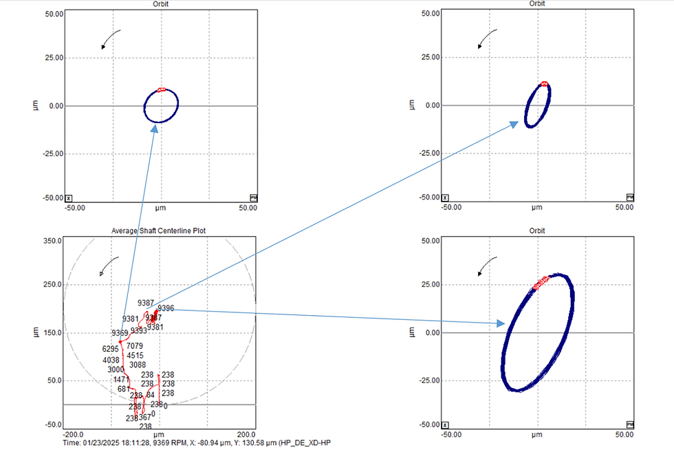
The change in the direction of the major axis Bearing 2’s orbit was detected at 30 MW as a result of bearing stiffness change caused by the piping strain as indicated in by shaft centerline plot with orbit overlay in Figure 2. The bearing lowered when output was reduced from 38 to 27 MW and then raised again as the output was further reduced to 13 MW as depicted in Figure 3.

Figure 2: Direct (blue) and synchronous (1X, orange) shaft orbits of Bearing 2

Figure 3: Orbit-overlayed shaft centerline plot during load decrease from 38 MW to no load
Remedy action and result
Even though the root cause of the problem is the piping strain, a stop-gap remedy action was needed to reduce the vibration amplitude for safe operation until the next planned outage. Since the orbit shape and 1X vibration amplitude/phase of both HP turbine bearings imply the possibility of field balancing. The influential coefficients from the previous field balancing were input in the in-house balancing spreadsheet to find the optimal weight and predicted the response vector as presented in Figure 4. The weight was placed at the HP turbine coupling and the maximum vibration amplitude of Bearing 2 was substantially decreased as shown by the amplitude trends plot of the HP rotor in Figure 5 and the comparison of shaft orbit at Bearing 2 in Figure 6. The unit was able to be operated at full capacity with sufficient margin to the trip setpoint.

Figure 4: Initial synchronous (1X) vibration vector and predicted vector after field balancing

Figure 5: Trend plot of overall shaft vibration of HP turbine and pinion after balancing

Figure 6: Direct (blue) and synchronous (1X, orange) shaft orbits of Bearing 2 before and after field balancing
Conclusions
In this case, field balancing can be time efficient stop-gap remedy action to reduce the vibration amplitude for safe operation until the next planned outage. However, the actual root cause of the piping strain must be rectified to solve the load-dependent vibration issue of the machine.

Comments