Troubleshooting: A Case Study of Electrostatic Discharge Affecting Rotor Dynamic Attributes
- PS

- Apr 22, 2024
- 4 min read
Updated: May 22, 2025

This article explains how to determine cause of journal bearing damage with erosion pattern as shown above.
Introduction:
As a machinery diagnostic services engineer, I recently experienced an interesting issue involving abnormal vibration and shaft centerline movement in a critical component of a 650 MW 50Hz steam turbine generator train. What followed was a fascinating journey of investigation, analysis, and discovery, ultimately leading to the identification of an unexpected culprit.

Fig 1 - Machine Train Diagram
The Problem:
The initial symptoms were unmistakable: abnormal vibration amplitudes and erratic shaft centerline movements at a journal bearing located at the non-drive end (NDE) of the exciter (bearing 9 in Fig 1). These anomalies raised immediate concerns about the integrity and performance of the machinery. Despite efforts to mitigate the issue, including thorough analysis using orbit plots, average shaft centerline movement, and trending of bearing temperatures, the root cause remained elusive.

Fig 2 - Trend plots of all shaft vibration amplitudes, showing abnormal changes at probe 9X and 9Y.

Fig 3 - Correlation between the shaft vibration amplitudes and the probe DC gap voltages. The gap voltage change implies changing relative shaft position within the journal bearing.

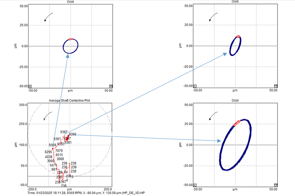
Fig 4 - Correlation between orbit shape and changing average shaft centerline position. Bearing initially pedestal movement is a suspected cause of problem. So, the pedestal locking is the first mitigative action.
The Investigation:
We took a close look and paid attention to every detail as we began a thorough investigation. What we found in the data was quite confusing: while vibration amplitudes showed some improvement after fixing the pedestal movement using additional locking bolts, the shaft centerline continued its erratic journey with transformed orbit shape as shown in the companying figure below.

Fig 5 - The trend plot of shaft vibration amplitudes, probe gab voltages, correlating with orbit plot and the moving shaft centerline position over five days period. It implies slowly developing problem type.

Fig 6 - Correlation between vibration amplitudes, probe gap voltages, and average shaft centerline position, recorded from problem initiation phase.
Based on our experience, this discrepancy hinted at a deeper underlying issue—one that required further exploration and analysis. According to basic theory, changing relative shaft centerline position over 300 microns implies misalignment issue. It is common that the rubbing problem is the first suspected symptom.
However, the rubbing problem likely to raise the vibration amplitudes (either at this measurement plane or others, depending on the rotor operating deflection shape) and quickly damages the bearing and drive the bearing metal temperature signals upward. This is not the case of facing problem as the bearing metal temperature was just 59 deg C as shown in following figure. Therefore, rubbing between shaft journal and bearing surfaces was unlikely the cause of problem.

Fig 7 - Trend plot of bearing metal temperatures during the moment of the problem.
The Discovery:
After watching closely and looking even harder, we made a big discovery. It turned out that the problem wasn't what we first thought. Instead of just the base of the bearing moving, the real issue was something unexpected: electricity zapping from the rotor to the bearing surface. This rare thing was slowly damaging the bearing, causing the problems we saw.
The supporting evidence that pointed to this phenomenon are listed below.
Tiny glitch spike traces on the orbit plots. These spike intermittently occurred and random angular location on the orbit plots.
Maintenance personnel observed electric sparks discharged from bearing hold-down bolts to the wrench.
Additional request to measure resistance between bearing pedestal and the reference grounding point was 90 Ohm, against the recommended value of 1 Mega-Ohm.
Voltage between shaft and ground point was 48 Vac and 15 Vdc, against specification of 0.16 Vac and 0.0 Vdc. This implies poor shaft grounding connection.

Fig 8 - Orbit plots, showing random spikes on the waveform. Mark No. 1 was recorded before the vibration increment. Mark No. 2 was recorded as the vibration reached highest level.
The Resolution:
Armed with this newfound understanding, we implemented targeted measures to address the issue. By implementing enhanced monitoring protocols and introducing protective measures against electrostatic discharge carried out by electrical experts, we successfully mitigated the problem, restoring optimal performance and reliability to the machinery.

Fig 9 - maintenance person was checking pedestal resistance. The value of 38.61 Mega-Ohm was measured after rectification.

Fig 10 - Showing the vibration amplitude became stable after rectification. The small spikes disappeared from the orbits.

Fig. 11 - Example of the journal bearing that was eroded from electrostatic discharge.
Conclusions:
The journey to uncovering the root cause of the abnormal vibration and shaft centerline movement was a testament to the intricacies of machinery diagnostics. Through meticulous analysis, observation, and perseverance, we unraveled the mystery and identified an unexpected culprit. This case study serves as a reminder of the importance of vigilance, thoroughness, and adaptability in addressing complex machinery challenges.
With relevant data plots, this blog aims to provide insight into the diagnostic process and highlight the importance of expertise in problem investigation for troubleshooting in ensuring the reliability and efficiency of critical machinery systems.

Comments