Torsional-Lateral Coupled Vibration in Geared Rotor Systems
- RC
- Feb 8
- 3 min read
Updated: Apr 2

Torsional vibration is often overlooked in field measurements due to installation challenges, limited reliability of instrumentation, and complexities in signal processing. However, torsional effects can couple into lateral (radial) vibration through gear mesh interactions, making them observable in conventional vibration data. This paper discusses the manifestation of torsional–lateral coupled vibration, excitation sources, measurement methodologies, and modeling approaches, with emphasis on practical case studies in turbomachinery.
1. Introduction
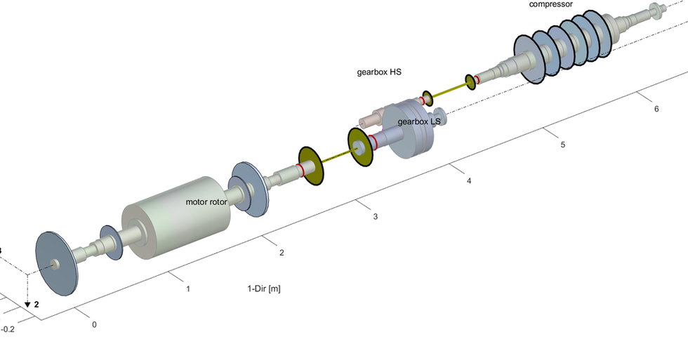
Torsional vibration is rarely measured in most machine trains operating in the field, primarily due to installation complexity, limited reliability of measurement systems, and difficulties in signal processing. Available instruments are generally intended for temporary installation or troubleshooting rather than continuous monitoring. Nevertheless, torsional vibration in a geared rotor system can often be inferred from conventional lateral vibration data, since torque fluctuations in the drive train couple through the gear mesh. In critical turbomachinery, shaft vibration sensors are typically installed at gearbox bearings, allowing indirect observation of torsional effects. During gear meshing, transmission torque generates two distinct forces: a separation (radial) force and a tangential force, both of which contribute to the coupled torsional–lateral vibration response.
2. Manifestation of Coupled Vibration
Torsional–lateral coupled vibration typically appears as subsynchronous vibration (SSV) when the first or second torsional natural frequency (TNF) is excited. These torsional modes are usually lower than the machine’s operating speed. Importantly, the observed frequency is distinct from other subsynchronous phenomena such as fluid-induced instability, aerodynamic instability, or partial rub conditions. Field experience shows that this behavior is often detected in gearbox vibration measurements of:
Integrally geared compressors
Steam turbine–generator sets
Gas turbine–generator sets
Motor-driven gas compressors


3. Excitation Sources
Multiple potential sources can excite torsional vibration, depending on machine type, installation, and surrounding environment. Identifying the root cause requires system-level analysis rather than focusing solely on machine vibration. Common excitation sources include:
Induction motors driven by variable frequency drives (VFDs)
Electric arc furnaces in steel processing plants
Gas, glycol, or chemical heaters with thyristor-based controllers
Abnormal load variations or malfunctioning load control mechanisms (e.g., inlet guide vane control)
Improper meshing in double-helical gears
4. Measurement and Analysis Methodology
A systematic approach is essential for torsional vibration analysis, since the phenomenon arises from interactions between the driver, driven equipment, and external systems such as the electrical grid. Based on extensive field experience, the following methodology is recommended:
Conventional vibration measurement: Radial (lateral) vibration sensors are permanently installed on most machine trains. Temporary measurements, such as casing vibration or laser keyphasers, can supplement data when required.
Torsional vibration measurement: For turbomachinery, strain gauge and telemetry systems or post-processing of high-sampled keyphaser signals using wavelet decomposition are effective. Non-contact torsional measurement systems have recently emerged but require further validation before field application.
Dynamic current measurement: When induction motors are drivers, monitoring supply current helps assess power quality. Electrical disturbances can induce torque fluctuations in the motor’s air gap.
Process variable data review: Correlating vibration data with process parameters (e.g., motor current, compressor load, oxygen flow in steel plants) is critical. Plant historian systems provide accessible records for such analysis.
5. Torsional Modeling and Analysis
Most machines are supplied with torsional analysis reports that include TNFs and interference/Campbell diagrams. However, mode shapes are often omitted, despite their importance in identifying which rotor sections undergo twisting at specific TNFs. When unavailable, torsional modeling is required.
A torsional model can be replicated from mass-elastics drawings, which are typically available on site. Once established, the model enables advanced studies such as forced response analysis and torsional–lateral coupled vibration analysis. These simulations provide valuable diagnostic insight and guide effective mitigation strategies.

6. Conclusions
Torsional-lateral coupled vibration remains a critical yet often underappreciated phenomenon in geared rotor systems. While direct measurement is challenging, systematic methodologies combining conventional vibration monitoring, torsional measurement, electrical analysis, and process data review can provide a comprehensive understanding. Replicated torsional models further enhance diagnostic capability, enabling engineers to identify mode shapes and perform advanced coupled analyses. Such approaches are essential for safeguarding the reliability of critical turbomachinery.


Comments