
Fluid induced instabilities – Whirl and Whip
Fluid-induced instabilities such as whirl and whip are critical self-excited vibration phenomena that challenge the reliability of high-speed rotating machinery. These instabilities arise from the dynamic interaction between the rotor and the circumferential fluid in bearings, seals, or any configuration where two cylinders rotate with fluid in the gap. Whirl typically manifests as a rigid-body forward precession orbit at frequencies near fluid resonance (λΩ) tracking with machine speed, while whip occurs when the rotor-bearing’s mechanical resonance coincides with whirl frequency, leading to unstable vibration growth with potential to reach physical limit such as bearing/seal clearances. The threshold speed is minimum speed which instability vibration occurs and it depends on fluid circumferential velocity (λ), rotor mass (m), and both rotor and bearing stiffness (k).
These problems are most often encountered in high-speed machines equipped with journal bearings, where fluid-rotor interactions can trigger instability at threshold speed. This article presents two case studies that illustrate the mechanisms of whirl and whip, and demonstrate diagnostic approaches to detect these instabilities in real machines. The findings highlight the importance of understanding fluid-rotor dynamics and stiffness characteristics to ensure safe and reliable operation of turbomachinery.
Introduction
Fluid-induced instabilities are among the most critical challenges in rotating machinery diagnostics. When oil-film forces inside bearings or seals interact with rotor dynamics, they can generate self-excited vibrations that compromise machine stability, reliability, and safety. Two well-known phenomena in this category are oil whirl and oil whip, both of which can lead to severe operational issues if not properly recognized and managed.
These instabilities are not only destructive but also deceptive appearing as circular orbits with forward precession that may resemble other vibration patterns. However, their vibration characteristics are distinct and can be clearly identified through full-spectrum cascade plots and orbit plots. Understanding these signatures is essential for both machine designers and end users, as early detection allows corrective action before damage occurs.
This article provides a practitioner-focused overview of whirl and whip, highlighting their vibration characteristics, threshold speed considerations, and practical solutions. By combining diagnostic tools with design and operational strategies, engineers can effectively mitigate fluid-induced instabilities and ensure reliable machine performance.
Vibration characteristics of whirl and whip
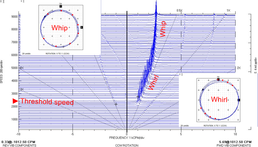
Detecting this problem is quite straightforward using vibration data since vibration characteristics of whirl and whip are very clear in full spectrum cascade and orbit plots as shown below. Whirl frequency is about 0.5X which is equal to λΩ and it is tracking with machine speed. The orbit shape is circular with forward precession since it is caused by oil/fluid wedge pushing the rotor to become unstable. In general, λ is close to 0.5 so that there are two keyphaser dots in each orbit meaning that the rotor is turning two revolutions to complete one vibration cycle. Keyphaser dots are changing opposite shaft rotation direction in each orbit since its frequency is slightly less than 0.5. For whip, it occurs when whirl frequency excites mechanical critical speed, hence, whip frequency is equal to mechanical critical speed of rotor-bearing system and it is locked at the same frequency with machine speed independence. This is typical a resonant vibration problem. The orbit shape remains circular but keyphaser dots are not divided into two group anymore as the frequency is now changed. Looking at full spectrum data, these two phenomena always show predominant forward precession at whirl and whip frequency components as a result of oil/fluid wedge inside the bearing or seal. Vibration characteristics are summarized below to easily recognize and detect these problems.
Whirl
· Vibration frequency at around 0.5X and tracking with machine speed
· Circular orbit shape with forward precession
· The rotor deflection shape remains rigid or low deflection.
Whip
· Vibration frequency reveals at mechanical resonance with machine speed independence (locked frequency)
· Circular orbit shape with forward precession
· The rotor deflects at mode shape (high deflection)
Threshold speed is minimum speed which fluid induced instability occur which should be above machine’s normal operating speed to avoid this problem. This threshold is depended on average oil/fluid circumferential velocity (λ), rotor and bearing stiffness (k), and rotor mass (m).
Since threshold speed is equal to (1/λ)*square root of (k/m), therefore, it can be increased by reducing oil/fluid circumferential velocity and/or increasing stiffness. In practical,
Similar vibration issues
In addition to oil whirl and oil whip, several other subsynchronous and unstable vibration phenomena can occur in rotating machinery. Recognizing these patterns is essential for accurate diagnostics and effective corrective action.
Surging and rotating stall are aerodynamic instabilities that occur in compressors or turbines, typically linked to flow separation and the formation of stall cells. These phenomena can arise even when machines are equipped with tilting‑pad bearings, since the root mechanism is aerodynamic rather than hydrodynamic. They are characterized by pressure fluctuations and oscillatory flow patterns, with vibration signatures that often appear subsynchronous and strongly coupled to blade natural frequencies. If left uncontrolled, surging and rotating stall can lead to resonant fatigue failure of blades, reduced efficiency, and serious reliability concerns in turbomachinery operation.
Subsynchronous rub occurs when mechanical contact develops between rotor and stator surfaces, typically due to clearance issues that allow intermittent interference. The vibration frequency appears at a modified mechanical resonance, often around twice the mechanical resonance frequency, and is accompanied by bouncing orbit shapes with impact signatures that reflect the rubbing action. This phenomenon generates high vibration amplitudes, localized heating, and can cause progressive damage to both rotor and casing surfaces if not corrected, making it a critical diagnostic concern in machinery operation.
Steam whirl is a fluid dynamic instability that occurs in steam turbines, particularly under high load conditions. It is typically triggered at 80–90% of full load in HP/IP turbines, where steam forces acting on the rotor generate subsynchronous vibration with forward precession. The phenomenon is strongly load-dependent, often disappearing when the machine operates at lower conditions. If not controlled, steam whirl can destabilize turbine operation, reduce reliability, and increase the risk of long-term damage to critical components.
Bearing pad fluttering is a dynamic instability that arises when bearing pads experience variable load conditions, producing vibration at a frequency not coincident with either fluid or mechanical resonance. The resulting orbit shapes are flat and unstable rather than circular with precession, making the phenomenon distinct from other subsynchronous instabilities. It is highly sensitive to operating parameters, particularly lube oil properties such as temperature and pressure, as well as bearing clearance, alignment, and changes in load distribution across the pads. If left unaddressed, bearing pad fluttering can lead to unpredictable vibration behavior and accelerated bearing wear, posing a serious reliability risk in rotating machinery.
Solutions
For Machine Designers
Change rotor configuration: Adjust length, diameter, or bearing span to shift critical speeds and improve stability.
Modify bearing or seal types: Select designs that reduce oil-film instability such as titling pad bearing or other non-circular bearing, honeycomb/hole pattern seal, swirl break, shut holes with center seal, etc.
Apply anti-swirl features: Fluid/gas injection in opposite shaft rotation direction to suppress fluid-induced forces (reducing fluid circumferential velocity).
Bearing machining: Optimize geometry to reduce hydrodynamic cross-coupling forces such as bearing machining to change length/diameter increasing specific bearing load.
External pressurized bearings: Introduce external damping and stiffness to stabilize the rotor system.
For End Users
Proper alignment and bearing clearance: Ensure installation tolerances are correct to minimize instability risk. This can ensure proper rotor eccentricity in the bearing, hence, proper stiffness, damping, and fluid circumferential velocity.
Maintain correct lube oil properties: Control oil temperature and pressure to sustain film stability.
Partial load control in steam turbines: Use valve management to avoid unstable operating regimes such as partial steam admission, etc.
Case study
Whirl in vertical hydro turbine-generator set
This case involves a 34 MW vertical hydro turbine-generator set equipped with a Francis runner, with two identical units installed at the same site. Both machines had recently undergone overhaul and realignment before being returned to service. Shortly after startup, excessive vibration amplitudes were observed at the upper guide bearing (UGB). In Unit 1, the instability appeared during transient startup, while in Unit 2 it occurred at full operating speed. Orbit and spectrum analysis confirmed that the root cause was oil whirl, but the difference in onset conditions between the two units was suspected to be related to alignment variations introduced during overhaul. The instability was driven by hydrodynamic forces in the bearing oil film, which reduced the threshold speed and allowed subsynchronous vibration to develop. To correct the problem, the bearing type was changed to tilting-pad bearings, which provided additional damping and stability by breaking up cross-coupling forces in the oil film. Following this modification, vibration amplitudes were significantly reduced, and both units operated stably across the full speed range, demonstrating the effectiveness of tilting-pad bearings in mitigating oil whirl in large hydro turbine-generator sets.


Whip in steam turbine-generator set
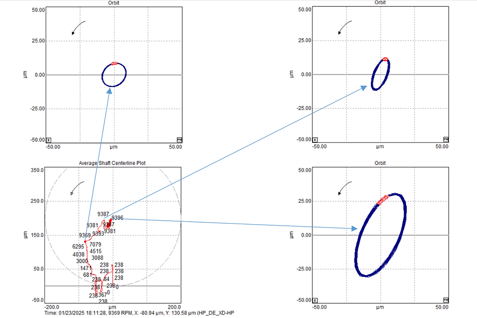
This case involves a condensing steam turbine-generator train consisting of a steam turbine with extraction, a speed-reduction gearbox, and a generator. The steam turbine operates at 5816 rpm with an overspeed trip set at 6398 rpm. Inlet steam conditions are 5.0 MPa(a) and 410 °C, with extraction steam at 1.8 MPa(a) and 8.3 t/h, and exhaust steam at 0.008 MPa(a). The gearbox has a speed ratio of 1.9388, driving a two-pole generator operating at 3000 rpm with an output of 9900 kW. Following a major overhaul and realignment, excessive subsynchronous vibration was detected at the generator bearing, which was diagnosed as oil whip. The instability was highly sensitive to alignment condition, with the rotor-bearing system locked at the critical speed independent of turbine operating speed. The corrective action involved realigning the unit so that the generator drive-end (DE) bearing carried more load, thereby increasing stability and suppressing the whip vibration. After this adjustment, the machine train operated reliably, demonstrating the importance of precise alignment in preventing oil whip in steam turbine-generator sets.


Conclusions
Fluid-induced instabilities such as oil whirl and oil whip remain critical concerns in the operation of rotating machinery. Their vibration characteristics are distinct and can be reliably detected through orbit plots and full-spectrum analysis, making early diagnosis achievable for practitioners equipped with proper monitoring tools. Whirl typically manifests at approximately half of running speed and is strongly influenced by oil-film dynamics, while whip occurs when whirl frequency excites the rotor’s mechanical critical speed, locking the vibration at resonance. Both phenomena highlight the importance of understanding subsynchronous vibration behavior and its dependence on alignment, bearing design, and lubrication conditions.
Beyond whirl and whip, similar vibration issues including surging, subsynchronous rub, steam whirl, and bearing pad fluttering demonstrate the wide range of instability mechanisms that can challenge machine reliability. Each has unique diagnostic signatures, reinforcing the need for careful interpretation of vibration data in context. Case studies from hydro and steam turbine-generator sets further illustrate how alignment condition and bearing type directly influence stability margins, and how corrective actions such as adopting tilting-pad bearings or redistributing bearing loads can restore reliable operation.
Ultimately, preventing fluid-induced instability requires a combined effort from both machine designers and end users. Designers must consider rotor configuration, bearing and seal selection, and stability-enhancing features, while plant users must maintain proper alignment, lubrication properties, and load control. By integrating diagnostic awareness with proactive design and operational practices, engineers can effectively mitigate these instabilities, safeguard equipment, and ensure long-term machine performance.


Comments