Rubbing in Turbomachinery
- RC
- Feb 28
- 8 min read

Rubbing occurs when rotating machine parts come into contact with stationary components. It is one of the most frequent malfunctions in rotating machinery, yet remains difficult to diagnose because vibration responses may appear as subsynchronous, synchronous, or supersynchronous (including harmonics). Accurate diagnosis requires a clear understanding of vibration characteristics, machine configuration, and dynamic behaviors that arise when rubbing forces are present. This article summarizes the nature of rubbing and highlights the vibration signatures associated with different rubbing conditions to support effective diagnostics and improved machinery reliability.
1. Introduction
Rubbing is generally considered a secondary malfunction, meaning it often arises as a consequence of other primary issues such as excessive vibration amplitude from unbalance, fluid-induced instabilities (whirl or whip), misalignment or pipe strain, uneven thermal expansion in steam or gas turbines, or insufficient clearances. Because rubbing is typically a symptom rather than the root cause, a systematic diagnostic approach is essential: whenever rubbing is suspected, the underlying primary malfunction must be identified and addressed.
At the rubbing interface, two fundamental forces are always present as friction and impact, each producing distinct consequences that shape the vibration response:
· Predominant friction force: Continuous friction generates localized heat at the rubbing point, leading to uneven thermal expansion around the rotor circumference. This thermal distortion causes the rotor to bow, creating a form of thermal unbalance. Since every rotor already possesses inherent mechanical unbalance, the effective unbalance becomes a combination of mechanical and thermal effects. The result is a change in the synchronous (1X) vibration response, both in amplitude and phase, as long as rubbing persists. This phenomenon is commonly referred to as thermal rub or the Newkirk effect.
· Predominant impact force: Impact excitation can trigger rotor-bearing natural frequencies (critical speeds), producing fractional vibration components at ½X, ⅓X, or ¼X depending on the operating speed relative to the critical speed. Because rubbing alters dynamic stiffness, the system becomes highly sensitive when operating near twice the critical speed. For instance, a ½X vibration may indicate rubbing that increases stiffness, or alternatively, looseness in bearings or supports that reduces stiffness. Correctly identifying the critical speed whether from nameplate data or transient vibration measurements is therefore vital for accurate diagnosis.
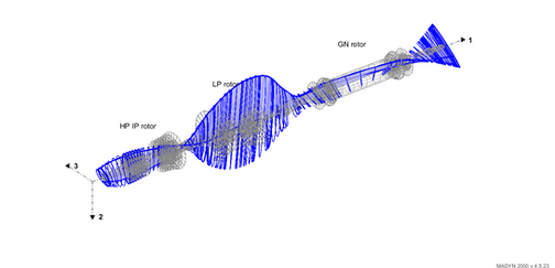
In flexible rotor machines, rubbing rarely occurs inside bearings, since these are typically located near nodal points with low rotor deflection and vibration amplitude. Instead, rubbing is most frequently observed at shaft seal regions such as oil seal rings, gland steam seals, or hydrogen/air seals depending on machine type. These areas experience higher rotor deflection and are therefore more prone to contact.


2. Subsynchronous Rub
Subsynchronous rubbing is primarily governed by impact forces and typically occurs when a machine operates at speeds greater than two times its critical speed. Under these conditions, the impact force excites the rotor-bearing system at its critical speed, producing fractional vibration frequencies such as ½X, ⅓X, or ¼X, depending on the ratio of running speed to critical speed.
The dynamic stiffness of the system strongly influences the vibration response. Rubbing can increase stiffness, while looseness in bearings or supports can reduce stiffness, both scenarios may result in a pronounced ½X vibration component when operating near twice the critical speed. Orbit plots in such cases often display rebounding or bouncing shapes, reflecting the intermittent impact mechanism at the rubbing interface.
This phenomenon can be effectively demonstrated using a rotor kit with a rubbing screw. By operating the rotor at approximately 2.5 times its critical speed and gradually adjusting the screw to contact the rotor surface, vibration spectra and orbit plots reveal the expected ½X frequency along with the characteristic bouncing orbit shape. Such experimental setups provide valuable insight into the mechanism of subsynchronous rub and its diagnostic signatures.
In practice, subsynchronous rubbing is frequently observed in high-speed steam turbines, gas compressors, and generators, where operating speeds are well above two times the critical speed and shaft seal regions are prone to contact. Recognizing the fractional frequency components and orbit behavior is therefore essential for accurate diagnosis and differentiation from other malfunctions such as fluid-induced instabilities or bearing looseness.

3. Synchronous Rub
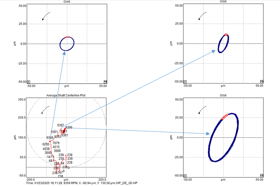
Synchronous rubbing is more likely when the machine operates at speeds below twice its critical speed. In this regime, friction forces dominate, producing a strong 1X vibration frequency. As rubbing persists, the rotor gradually bows due to thermal unbalance, and the orbit shape evolves from slightly elliptical to nearly circular. Both the amplitude and phase of the 1X vibration continue to vary, reflecting the evolving combination of thermal and mechanical unbalance. If vibration becomes excessive and the unit trips, evidence of rotor bow can be confirmed by high 1X slow-roll/runout and a shift in the rotor heavy spot.

In steam turbines, synchronous rub often occurs during startup after major overhauls, particularly when gland steam seals are replaced. Tight clearances and uneven thermal expansion between rotor and casing increase the risk. To mitigate this, startup curves may be modified at heat-soaking speeds, which allow thermal equalization and reduce rubbing risk. Continuous vibration monitoring during startup is critical, along with tracking process variables such as casing expansion, differential expansion, rotor eccentricity, casing temperature, steam temperature, and pressure. Documenting successful parameter profiles for cold, warm, and hot startups helps ensure reliable operation and minimizes delays in returning the unit to service.

Intermittent Rub
Intermittent synchronous rub refers to similar symptoms appearing in a random manner. This is often caused by coke accumulation at oil seal rings, which tightens seal clearance and leads to rubbing. Vibration amplitude increases initially, then decreases once the coke is wiped off, repeating as accumulation recurs. Coke forms when lubricating oil contacts hot steam or exhaust gas, evaporating the liquid portion and leaving solid carbon, a process sometimes referred to as carbonized oil. This typically results from malfunction vacuum gland steam seals, buffering air/nitrogen systems, or heat barriers around oil seal rings. Similar issues have been reported in power recovery turbines (PRT) in refinery plants, where high-temperature waste fluids promote carbonization.

Third-Support Effect
Rubbing can act as an additional support point for the rotor (sometimes called a “third support”), significantly increasing dynamic stiffness and shifting the critical speed. In such cases, startup data may misleadingly suggest that the unit does not pass through critical speed, since the peak amplitude and ~90° phase shifted are absent, the critical speed has significantly moved above the machine’s operating speed range. This phenomenon has been reported in gas compressors with wet seals installed, where oil-lubricated sealing elements lock and behave like an additional bearing. However, this symptom is rarely encountered today, as most modern gas compressors use dry gas seals, which have minimal influence on vibration response.
Heavy Rub
In cases of severe/heavy rubbing, orbit plots show truncated or obstacle-like shapes, accompanied by harmonic vibration frequency components. This behavior results from the nonlinear vibration response, where the fast Fourier transform (FFT) of a modified sinewave reveals multiple harmonics.

Rubbing at Generator Slip Rings
Generators equipped with carbon brushes for excitation current transfer can sometimes exhibit vibration characteristics similar to rubbing. Carbon brushes are low-friction, conductive, self-lubricating, and durable, but friction between the rotor and brushes can cause rolling 1X phase angles and minor amplitude variations. Heat generation at localized “hot spots” may further influence vibration. In practice, vibration amplitude changes are often small, and operators may overlook the issue since many control systems monitor only amplitude. Different manufacturers use varying carbon brush materials and grades, which can produce distinct friction levels and vibration patterns.

4. Similar Malfunctions
Rubbing shares several vibration characteristics with other turbomachinery malfunctions, which can complicate diagnosis. A clear understanding of these similarities and differences is essential for accurate fault identification:
Bearing Looseness
Produces subsynchronous vibration, often at ½X frequency, due to reduced dynamic stiffness. Sub-harmonics and harmonics can be expected in case of journal loose inside the housing.
Occurs when the unit operates slightly less than two times its critical speed.
Orbit plots may show irregular or flattened shapes resembling rubbing impact forces.
Unlike rubbing, looseness typically exhibits sudden amplitude jumps when load changes.
Fluid-Induced Instabilities (Whirl/Whip)
Whirl occurs near the oil-film natural frequency (λΩ), typically subsynchronous.
Whip locks onto the rotor-bearing critical speed (mechanical resonance), producing a constant subsynchronous frequency independent of running speed.
Orbit shape is circular with mainly forward precession and amplitude close to bearing clearance.
Morton Effect
A thermal instability caused by asymmetric heating of the rotor due to journal bearing oil-film effects.
Produces a slowly increasing 1X vibration amplitude and phase rolling, similar to thermal rub.
Distinguished by its dependence on bearing design and oil-film behavior, rather than direct rotor-to-stator contact.
It is mostly likely noticed on overhung rotor machine such as integrally geared compressor, etc.
Change in lube oil supply temperature and/or pressure should affect to vibration response.
Aerodynamic Instability
Common in compressors and turbines where flow separation or vortex shedding excites rotor dynamics.
Can produce subsynchronous vibrations resembling impact rub.
Typically linked to operating conditions such as high load or off-design flow regimes.
This type of instability tends to be captured during machine design phase when rotordynamics modeling and analysis is performed.
Compressor Surging and Stalling
Surging produces large-amplitude, low-frequency oscillations in pressure and flow, which can couple into rotor vibration.
Stalling causes localized flow instabilities, sometimes exciting blade-pass frequencies or subsynchronous components.
These phenomena can mimic rubbing signatures but are usually accompanied by process variable fluctuations (pressure, flow)
Review operating point on compressor against surge control line and action of recycle valve would help to narrow down the possibility.
Bearing Pad Fluttering
Occurs when tilting-pad bearings experience dynamic instability due to pad motion.
Produces subsynchronous vibration components similar to looseness or rub. But however, the frequency is not coincident with critical speed.
Orbit shape is irregularly flattened.
Distinguished by its dependence on bearing geometry, preload, and lubrication conditions.
Change in lube oil supply temperature and/or pressure can affect vibration response.
5. Diagnosing Rub
Effective diagnosis of rubbing requires a structured, multi-faceted approach that integrates vibration analysis, operational data, and physical inspection. Because rubbing often overlaps with other malfunctions, a disciplined workflow is essential:
Comprehensive Machine Understanding
Develop a clear knowledge of the machine’s configuration, components, and process effects on vibration behavior.
Key factors include seal types, working fluid temperature, thermal expansion characteristics, and critical speed data.
Reference materials such as sectional drawings, nameplate data sheets, and rotordynamics reports provide invaluable context.
Vibration Spectrum Analysis
Identify fractional frequencies (½X, ⅓X, ¼X) that indicate impact-dominated rub.
Monitor 1X amplitude and phase drift for friction-dominated rub (thermal bow).
Compare startup and shutdown spectra to detect transient rub events.
Orbit Analysis
Subsynchronous rub: orbit plots often show bouncing or rebounding shapes due to impact forces.
Synchronous rub: orbits gradually transition from elliptical to circular as thermal bow increases.
Orbit plots provide strong visual confirmation of rubbing mechanisms and help distinguish them from other malfunctions.
Transient Data Monitoring
Track vibration behavior during startup, shutdown, and load changes.
Correlate vibration trends with process variables such as casing expansion, differential expansion, steam temperature, steam pressure, and exhaust gas temperature spread in gas turbines.
Compare against documented healthy startup profiles to identify abnormal deviations.
Physical Inspection
Examine shaft seals, oil rings, and gland seals for wear marks, scoring, or discoloration.
Verify clearances against design tolerances to confirm whether rubbing contact is possible.
Inspection findings provide direct evidence to validate vibration-based diagnosis.
6. Conclusions
Rubbing in turbomachinery is a complex secondary malfunction that can manifest as either subsynchronous or synchronous vibration, depending on whether impact forces or friction forces dominate. Because rubbing often arises from underlying issues such as unbalance, misalignment, fluid instabilities, or insufficient clearances, accurate diagnosis requires a disciplined and comprehensive approach.
Key diagnostic principles include:
Recognizing vibration signatures: friction rub produces thermal bow effects with evolving 1X amplitude and phase, while impact rub generates fractional frequencies (½X, ⅓X, ¼X) and bouncing orbit shapes.
Differentiating rubbing from similar malfunctions such as bearing looseness, fluid-induced instabilities, Morton effect, aerodynamic instabilities, or compressor surging.
Employing a systematic workflow that integrates vibration spectra, orbit plots, transient monitoring, and physical inspection to validate findings.
Documenting startup and shutdown profiles to establish reliable baselines, enabling early detection of abnormal trends and reducing diagnostic uncertainty.
Ultimately, effective diagnosis of rubbing depends on systematic monitoring and disciplined diagnostic practices. By carefully analyzing the mechanisms, vibration characteristics, and diagnostic signatures of rubbing, engineers can distinguish it from similar malfunctions, identify underlying causes, and apply corrective measures. This structured approach helps minimize downtime, prevent secondary damage, and ensure the reliable operation.


Comments